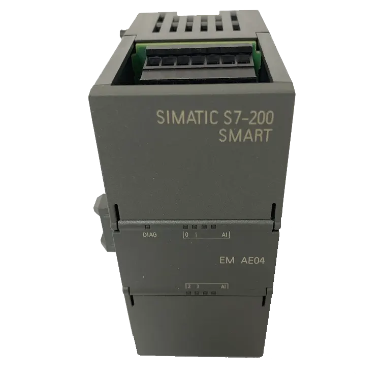
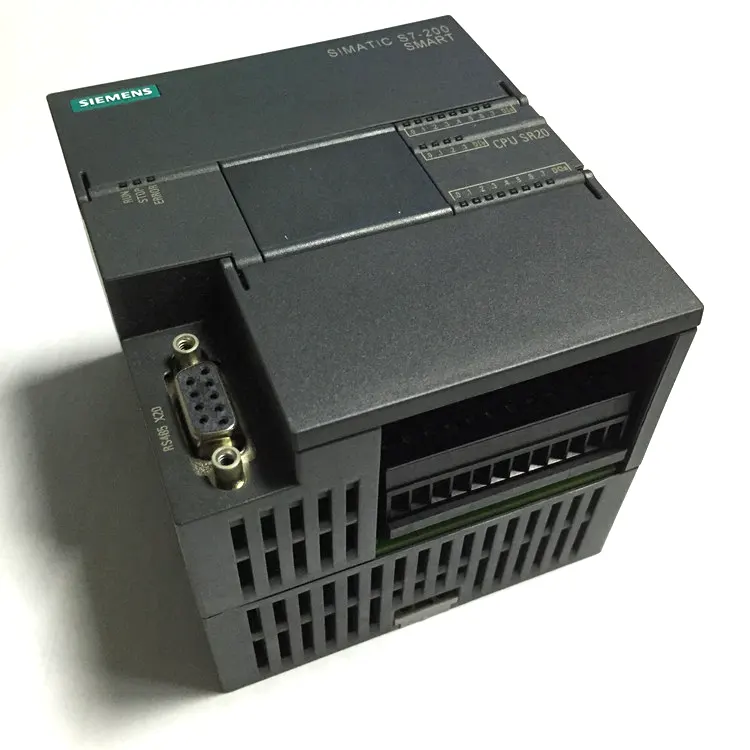
Siemens PLC Module 6ES7288-1SR20-0AA1 SIMATIC S7-200 SMART Analog I/O SM AM06 4 AI/2 AO
6ES7288-1SR20-0AA1
| 6ES72881SR200AA1: S7-200 SMART, CPU SR20, Standard CPU Module, Relay Output, 220 VAC Power Supply, 12 Inputs/8 Outputs |
| 6ES72881ST200AA1: S7-200 SMART, CPU ST20, Standard CPU Module, Transistor Output, 24 VDC Power Supply, 12 Inputs/8 Outputs |
| 6ES72881SR300AA1: S7-200 SMART, CPU SR30, Standard CPU Module, Relay Output, 220 VAC Power Supply, 18 Inputs/12 Outputs |
| 6ES72881ST300AA1: S7-200 SMART, CPU ST30, Standard CPU Module, Transistor Output, 24 VDC Power Supply, 18 Inputs/12 Outputs |
| 6ES72881SR400AA1: S7-200 SMART, CPU SR40, Standard CPU Module, Relay Output, 220 VAC Power Supply, 24 Inputs/16 Outputs |
| 6ES72881ST400AA1: S7-200 SMART, CPU ST40, Standard CPU Module, Transistor Output, 24 VDC Power Supply, 24 Inputs/16 Outputs |
| 6ES72881SR600AA1: S7-200 SMART, CPU SR60, Standard CPU Module, Relay Output, 220 VAC Power Supply, 36 Inputs/24 Outputs |
| 6ES72881ST600AA1: S7-200 SMART, CPU ST60, Standard CPU Module, Transistor Output, 24 VDC Power Supply, 36 Inputs/24 Outputs |
| 6ES72881CR200AA1: S7-200 SMART, CPU CR20S, Economy CPU Module, Relay Output, 220 VAC Power Supply, 12 Inputs/8 Outputs |
| 6ES72881CR300AA1: S7-200 SMART, CPU CR30S, Economy CPU Module, Relay Output, 220 VAC Power Supply, 18 Inputs/12 Outputs |
| 6ES72881CR400AAD: S7-200 SMART, CPU CR40, Economy CPU Module, Relay Output, 220 VAC Power Supply, 24 Inputs/16 Outputs |
| 6ES72881CR600AAD: S7-200 SMART, CPU CR60, Economy CPU Module, Relay Output, 220 VAC Power Supply, 36 Inputs/24 Outputs |
| Technical Specification | CPU SR20 Specifications | CPU ST20 Specifications |
|---|---|---|
| Model | CPU SR20 | CPU ST20 |
| Order Number (MLFB) | 6ES7288-1SR20-0AA1 | 6ES7288-1ST20-0AA1 |
| Dimensions W×H×D (mm) | 90x100x81 | 90x100x81 |
| Weight (g) | 367.3 | 320 |
| Power Consumption (W) | 14 | 12 |
| Available Current (24 V DC) (mA) | Max 300 (sensor power supply) | Max 300 (sensor power supply) |
| Digital Input Current Consumption (24 V DC) | 4 mA per input used | 4 mA per input used |
| User Memory | 12KB program memory/8KB data memory/max 10KB retainable memory | 12KB program memory/8KB data memory/max 10KB retainable memory |
| Onboard Digital I/O | 12 inputs/8 outputs | 12 inputs/8 outputs |
| Process Image Size | 256 bits input (I)/256 bits output (Q) | 256 bits input (I)/256 bits output (Q) |
| Analog Image | 56 words input (AI)/56 words output (AQ) | 56 words input (AI)/56 words output (AQ) |
| Bit Memory (M) | 256 bits | 256 bits |
| Temporary (Local) Memory | 64 bytes in main program, 64 bytes in each subroutine and interrupt program | 64 bytes in main program, 64 bytes in each subroutine and interrupt program |
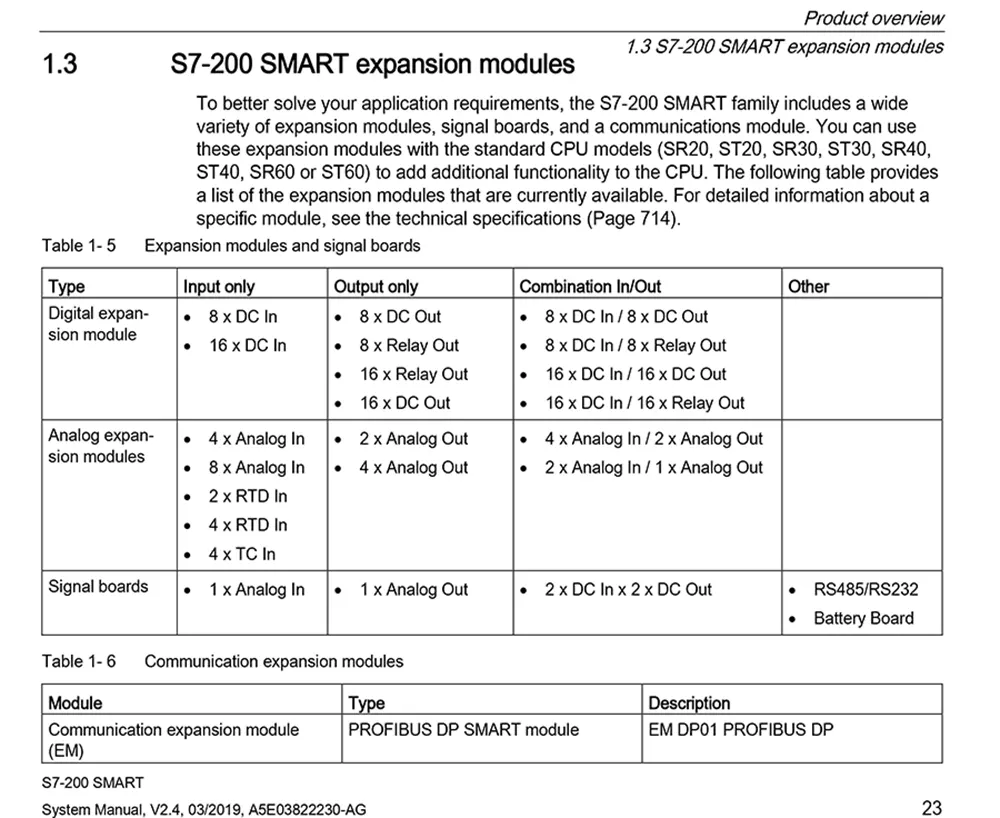
| I/O Module Expansion | 6 expansion modules | 6 expansion modules |
| Signal Board Expansion | Up to 1 signal board | Up to 1 signal board |
| High-Speed Counters | Total 6 | Total 6 |
| Pulse Output | – | 2 x 100 KHz |
| Pulse Capture Inputs | 12 | 12 |
| Cycle Interrupts | Total 2, with 1 ms resolution | Total 2, with 1 ms resolution |
| Edge Interrupts | 4 rising edges and 4 falling edges (6 each when optional signal board is used) | 4 rising edges and 4 falling edges (6 each when optional signal board is used) |
| Memory Card | Micro SDHC card (optional) | Micro SDHC card (optional) |
| Real-Time Clock Accuracy | ±120 seconds/month | ±120 seconds/month |
| Real-Time Clock Hold Time | Typically 7 days, minimum 6 days at 25°C (maintenance-free supercapacitor) | Typically 7 days, minimum 6 days at 25°C (maintenance-free supercapacitor) |
| Boolean Operations | 0.15 μs/instruction | 0.15 μs/instruction |
| Move Word | 1.2 μs/instruction | 1.2 μs/instruction |
| Floating-Point Math Operations | 3.6 μs/instruction | 3.6 μs/instruction |
| POU Types | Main program: 1 Subroutines: 128 (0 to 127) Interrupt programs: 128 (0 to 127) | Main program: 1 Subroutines: 128 (0 to 127) Interrupt programs: 128 (0 to 127) |
| Nesting Depth | From main program: 8 subroutine levels From interrupt program: 4 subroutine levels | From main program: 8 subroutine levels From interrupt program: 4 subroutine levels |
| Accumulators | 4 | 4 |
| Timer Types | Non-retentive (TON, TOF): 192 Retentive (TONR): 64 | Non-retentive (TON, TOF): 192 Retentive (TONR): 64 |
| Counters | 256 | 256 |
| Ports | PROFINET (LAN): 1 | PROFINET (LAN): 1 |
| Serial Ports | 1 (RS485) | 1 (RS485) |
| Additional Serial Ports | 1 (with optional RS232/485 signal board) | 1 (with optional RS232/485 signal board) |
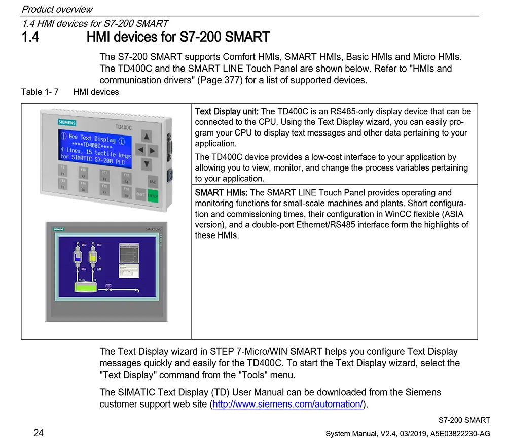
| HMI Connections | PROFINET (LAN): 8 connections Serial port: 4 connections per port | PROFINET (LAN): 8 connections Serial port: 4 connections per port |
| Programming Device (PG) Connections | Serial port: 1 connection PROFINET (LAN): 1 connection | Serial port: 1 connection PROFINET (LAN): 1 connection |
| CPU (PUT/GET) Connections | PROFINET (LAN): 8 clients and 8 servers | PROFINET (LAN): 8 clients and 8 servers |
| PROFINET Communication | PROFINET controller: Yes | PROFINET controller: Yes |
| Max PROFINET Devices for RT Connections | 8 | 8 |
| Max Modules | 64 | 64 |
| PROFINET Smart Device | Yes | Yes |
| Open User Communications | PROFINET (LAN): 8 active and 8 passive connections | PROFINET (LAN): 8 active and 8 passive connections |
| Data Transfer Rate | 10/100 Mb/s | 10/100 Mb/s |
| RS485 System Protocols | 9600, 19200, and 187500 b/s | 9600, 19200, and 187500 b/s |
| RS485 Free Port | 1200 to 115200 b/s | 1200 to 115200 b/s |
| Isolation (External Signals to PLC Logic Side) | PROFINET (LAN): Galvanic isolator, 1500 VAC | PROFINET (LAN): Galvanic isolator, 1500 VAC |
| Cable Types | Ethernet: CAT5e shielded cable | Ethernet: CAT5e shielded cable |
| Voltage Range | 85 to 264 VAC 77 to 138 VDC 20.4 to 28.8 VDC | 85 to 264 VAC 77 to 138 VDC 20.4 to 28.8 VDC |
| Power Frequency | 47 to 63 Hz | 47 to 63 Hz |
| Surge Current (Max) | 9.3 A at 264 VAC 11.7 A at 28.8 VDC | 9.3 A at 264 VAC 11.7 A at 28.8 VDC |
| Isolation (Input Power to Logic Side) | 1500 VAC – | 1500 VAC – |
| Leakage Current, AC Line to Functional Earth | Max 0.5 mA – | Max 0.5 mA – |
| Hold Time (Power Failure) | 30 ms at 120 VAC 30 ms at 110 VDC 20 ms at 24 VDC 200 ms at 240 VAC | 30 ms at 120 VAC 30 ms at 110 VDC 20 ms at 24 VDC 200 ms at 240 VAC |
| Internal Fuse (Non-User Replaceable) | 3 A, 250 V, slow-blow | 3 A, 250 V, slow-blow |
| Sensor Power Supply | 20.4 to 28.8 VDC | 20.4 to 28.8 VDC |
| Rated Output Current (Max) | 300 mA (short-circuit protected) | 300 mA (short-circuit protected) |
| Max Ripple Noise (<10 MHz) | <1 V peak-to-peak | <1 V peak-to-peak |
| Isolation (CPU Logic Side to Sensor Power Supply) | Not isolated | Not isolated |
| Digital Inputs | 12 | 12 |
| Type | Sinking/sourcing (IEC Type 1 sinking) | Sinking/sourcing (IEC Type 1 sinking) |
| Sinking/Sourcing (IEC Type 1 Sinking, Except 10.0 to 10.3) | Sinking/sourcing (IEC Type 1 sinking, except 10.0 to 10.3) | |
| Rated Voltage | 24 VDC at 4 mA, rated | 24 VDC at 4 mA, rated |
| Allowed Continuous Voltage | Max 30 VDC | Max 30 VDC |
| Surge Voltage | 35 VDC for 0.5 s | 35 VDC for 0.5 s |
| Logic 1 Signal (Min) | 15 VDC at 2.5 mA 4 VDC at 8 mA for 10.0 to 10.3, 10.6 to 10.7 15 VDC at 2.5 mA for other inputs | 15 VDC at 2.5 mA 4 VDC at 8 mA for 10.0 to 10.3, 10.6 to 10.7 15 VDC at 2.5 mA for other inputs |
| Logic 0 Signal (Max) | 5 VDC at 1 mA 1 VDC at 1 mA for 10.0 to 10.3, 10.6 to 10.7 5 VDC at 1 mA for other inputs | 5 VDC at 1 mA 1 VDC at 1 mA for 10.0 to 10.3, 10.6 to 10.7 5 VDC at 1 mA for other inputs |
| Isolation (Field Side to Logic Side) | 500 VAC for 1 min | 500 VAC for 1 min |
| Isolation Group | 1 | 1 |
| Filter Time | Individually selectable per channel (points 10.0 to 11.3): | Individually selectable per channel (points 10.0 to 11.3): |
| 0.2, 0.4, 0.8, 1.6, 3.2, 6.4, and 12.8 μs | 0.2, 0.4, 0.8, 1.6, 3.2, 6.4, and 12.8 μs | |
| 0.2, 0.4, 0.8, 1.6, 3.2, 6.4, and 12.8 ms | 0.2, 0.4, 0.8, 1.6, 3.2, 6.4, and 12.8 ms | |
| HSC Clock Input Frequency (Max) | Single-phase: 4 x 200 KHz + 2 x 30 KHz Quadrature phase: 2 x 100 KHz + 2 x 20 KHz | Single-phase: 4 x 200 KHz + 2 x 30 KHz Quadrature phase: 2 x 100 KHz + 2 x 20 KHz |
| Digital Outputs | 8 | 8 |
| Type | Relay, dry contact | Solid-state – MOSFET (sourcing) |
| Voltage Range | 5 to 30 VDC or 5 to 250 VAC | 20.4 to 28.8 VDC |
| Logic 1 Signal at Max Current | – | Min 20 VDC |
| Logic 0 Signal with 10 KΩ Load | – | Max 0.1 VDC |
| Rated Current per Point (Max) | 2.0 A | 0.5 A |
| Rated Current per Common (Max) | 10.0 A | 6 A |
| Lamp Load | 30 W DC/200 W AC | 5 W |
| On-State Resistance | Max 0.2 Ω for new devices | Max 0.6 Ω |
| Leakage Current per Point | – | Max 10 μA |
| Surge Current | 7 A for contact closure | 8 A, max 100 ms duration |
| Overload Protection | None | None |
| Isolation (Field Side to Logic Side) | 1500 VAC for 1 min (coil to contacts), none (coil to logic side) | 500 VAC for 1 min |
| Isolation Resistance | Min 100 MΩ for new devices | Min 100 MΩ for new devices |
| Dielectric Strength Between Open Contacts | 750 VAC for 1 min – | 750 VAC for 1 min – |
| Isolation Group | 1 | 2 |
| Inductive Clamping Voltage | Not recommended | L+ – 48 VDC, 1 W dissipation |
| Relay Max Switching Frequency | Not recommended | Not recommended |
| Switching Delay (Qa.0-Qa.3) | Max 10 ms | Max 10 ms |
| Off-to-On Max | 1.0 μs | 50 μs |
| On-to-Off Max | 3.0 μs | 200 μs |
| Switching Delay (Qa.0-Qa.7) | Max 10 ms | Max 10 ms |
| Off-to-On Max | 50 μs | 1.0 μs |
| On-to-Off Max | 200 μs | 3.0 μs |
| Mechanical Life (No Load) | 10,000,000 open/close cycles | 10,000,000 open/close cycles |
| Contact Life at Rated Load | 100,000 open/close cycles | 100,000 open/close cycles |
| STOP Mode Output State | Last value or replacement value (default is 0) | Last value or replacement value (default is 0) |
| Simultaneously On Outputs | 8 | 8 |
| Cable Length | Shielded: 500 m Unshielded: 300 m | Shielded: 500 m Unshielded: 300 m |